DX5
200V AC Servo Drive Systems
D0500 | D0504 | D0508
Introducing DX5... Trio's 200V ac (3-phase) multi-axis servo drive

At A Glance
- DX5 drives and Trio's motion controller fully integrated into Motion Perfect
- EtherCAT network for motion control
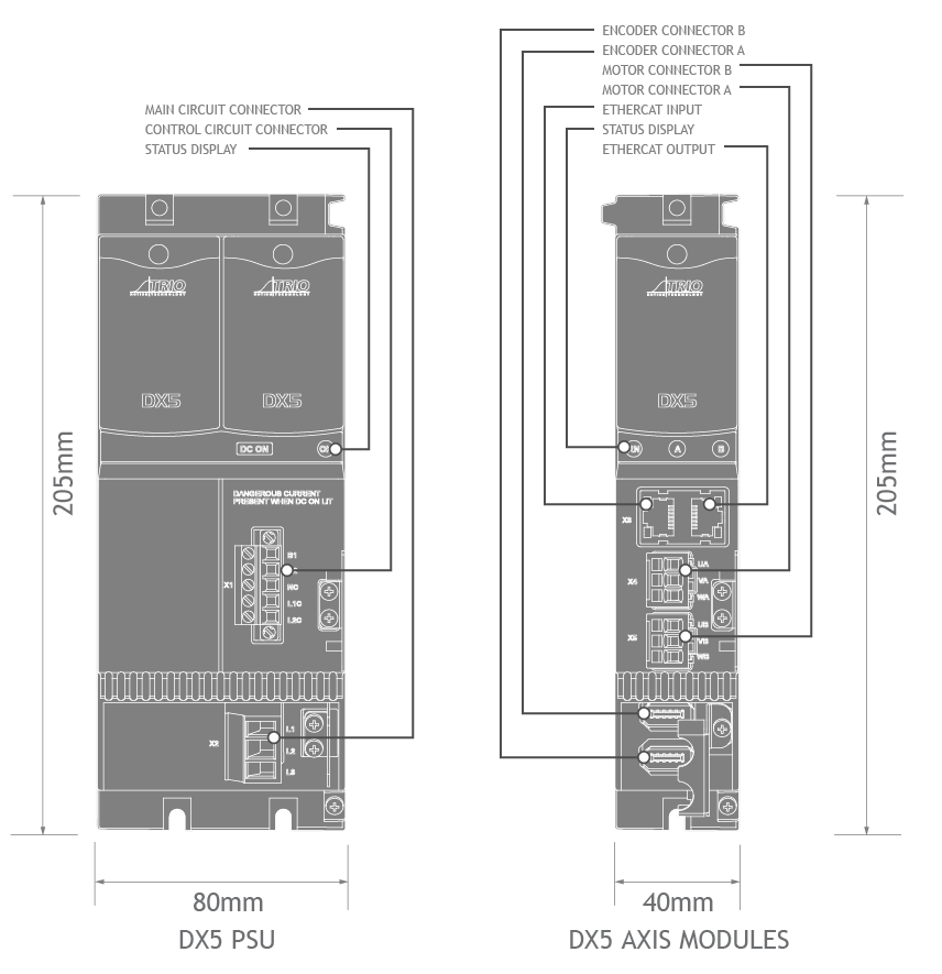
- Zero stacking gap installation
- Optimized for multi-axis machines
- 200V ac (3-phase) supply module
- Dual 750W axis module, supporting 750W and 400W motors
- Dual 400W axis module, supporting 400W, 200W and 100W motors
- 23-bit multi-turn absolute encoder
- 350% overload
- Internal drive protection functions
- Comprehensive tuning technology
- Field upgradable firmware
- Matched with MXL motors
- IO functions handled by motion controller as part of the DX series ‘Everything you need nothing more’ concept
DX5 is designed to work seamlessly with Trio's controllers and is fully integrated into Trio’s application development tool, Motion Perfect. It comes in power ratings from 400W to 750W. Matched with the MXL motors it offers a high-speed, high-precision machine solution.
Download DX5 System Brochure
DX5 dual axis drive modules come in 2 compact frame sizes and combined with the power supply units can be configured for up to 16 axes with power ratings from 400W to 750W. Designed to be matched with the MXL motors and accessories it offers a high-speed, high-precision machine solution.
The DX5 is designed to work seamlessly with Trio's EtherCAT controllers and be fully integrated into Trio’s application development tool, Motion Perfect allowing complete machine configuration from one tool; commissioning, diagnostics and programming.
With a focus on ease of use, the DX5 minimises setup time allowing you to focus on your application.
Space Efficient
Highly compact compared to standalone AC powered servo drives solution. AC power cabling and system wiring reduced by up to 80%.
Integration Efficient
Rapid application development of controller and drive configuration within Motion Perfect.
Design Efficient
One system to program, simplifying development and any future production changes needed.
Energy Efficient
DC Bus regenerative energy is reused by the system. Energy savings for the life of the system, motor braking is absorbed and reused by all axes.
EVERYTHING YOU NEED... NOTHING MORE.